Maintaining your Mercedes-Benz Sprinter van in peak condition requires understanding its intricate systems, and the electrical system is paramount. A crucial component of this system is the fuse box, which protects your van’s circuits from overload. This article, brought to you by the experts at benzxentry.store, your trusted source for automotive repair knowledge, delves into the fuse box diagrams for the second-generation Mercedes-Benz Sprinter (W906, NCV3), produced from 2006 to 2018.
Whether you’re troubleshooting an electrical issue or simply want to familiarize yourself with your Sprinter’s layout, this guide provides detailed fuse box diagrams, fuse locations, and assignments for Mercedes-Benz Sprinter models from 2006, 2007, 2008, 2009, 2010, 2011, 2012, 2013, 2014, 2015, 2016, 2017, and 2018. Understanding your Mercedes Sprinter fuse box diagram is essential for any Sprinter owner or mechanic.
Decoding Your Mercedes Sprinter Fuse Boxes
The Mercedes-Benz Sprinter W906 (NCV3) features several fuse boxes strategically placed throughout the vehicle. For easy navigation, we’ll break down each location and provide clear diagrams and fuse allocation charts. This guide will cover the main fuse box located inside the instrument panel, the fuse box under the driver’s seat, and the pre-fuse boxes.
For instance, if you’re experiencing issues with your cigar lighter (power outlet) fuses in the Mercedes-Benz Sprinter, you’ll need to check fuses #13 and #25 in the Instrument panel fuse box, and fuses #23, #24, and #25 in the Fuse Box under driver’s seat. This detailed breakdown ensures you can quickly pinpoint the relevant fuse box for your specific electrical component.
Instrument Panel Fuse Box (Main Fuse Box)
The instrument panel fuse box, often considered the main fuse box, is easily accessible and houses fuses for many of the Sprinter’s interior electrical functions.
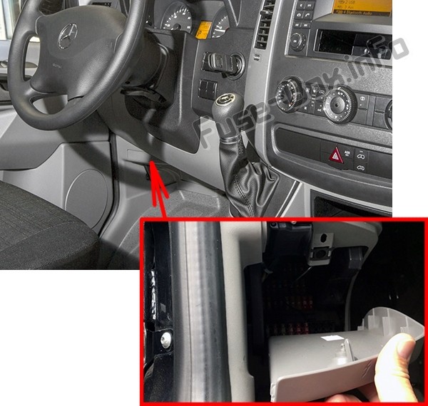
Location of the Instrument Panel Fuse Box
The instrument panel fuse box location is situated beneath the dashboard on the driver’s side. You can access it by removing the cover panel, usually requiring no tools for quick access.
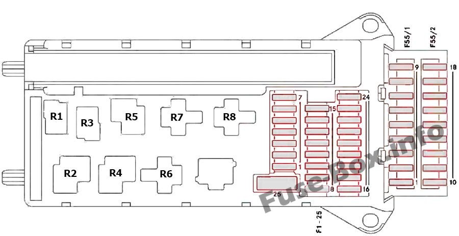
Instrument Panel Fuse Box Diagram and Fuse Layout
Below is a detailed Mercedes Sprinter instrument panel fuse box diagram illustrating the position and function of each fuse and relay. Refer to this diagram to identify the specific fuse related to your electrical problem.
Instrument Panel Fuse and Relay Assignment Chart
| # | Consumer | Amp |
|---|---|---|
| 1 | Horn | 15 |
| 2 | ESTL (electric steering lock) ignition lock | 25 |
| 3 | Terminal 30 Z, vehicles with a gasoline engine/ ignition lock/instrument cluster | 10 |
| 4 | Light switch/switch unit on center console | 5 |
| 5 | Windshield wipers | 30 |
| 6 | Fuel pump Terminal 87 (5) (Vehicles with code MI6/MH3/XM0) | 15/10 |
| 7 | MRM (jacket tube module) | 5 |
| 8 | Terminal 87 (2) | 20 |
| 9 | Terminal 87 (1) Terminal 87 (3), vehicles with a gasoline engine Terminal 87 (3), vehicles with a diesel engine | 25/20/25 |
| 10 | Terminal 87 (4) | 10 |
| 11 | Terminal 15 R vehicle | 15 |
| 12 | Air bag control unit | 10 |
| 13 | Cigarette lighter/glove box lamp/radio/body manufacturer loading tailgate/PND (personal navigation device) power socket | 15 |
| 14 | Diagnostics connection/light switch/instrument cluster/deactivating reverse warning device/anti-theft protection with vehicle tracking | 5 |
| 15 | Headlamp range con- trol/front-compartment heating | 5 |
| 16 | Terminal 87 (1) Terminal 87 (3) (Vehicles with code MI6/MH3/XM0) | 10 |
| 17 | Air bag control unit | 10 |
| 18 | Terminal 15 vehicle/ brake light switch | 7.5 |
| 19 | Interior lighting | 7.5 |
| 20 | Front-passenger door power window switch/ terminal 30/2 SAM (signal acquisition and actuation module) | 25 |
| 21 | Engine control unit | 5 |
| 22 | Brake system (ABS) | 5 |
| 23 | Starter motor Terminal 87 (6) (Vehicles with code MI6/MH3/XM0) | 20/10 |
| 24 | Diesel engine, engine components/control unit, vehicles with a natural gas engine NGT (Natural Gas Technology) | 10 |
| 25 | 12 V socket (center console) for tire sealant | 25 |

Fuse Block F55/1
| # | Consumer | Amp |
|---|---|---|
| 1 | Driver’s door control unit | 25 |
| 2 | Diagnostics connection | 10 |
| 3 | Brake system (valves) | 25 |
| 4 | Brake system (delivery pump) | 40 |
| 5 | Terminal 87 (2a) engine M272, OM651 | 7.5 |
| 6 | Terminal 87 (1a) engine OM6426 (Vehicles with code XM0) Terminal 87 (1a) engine OM651 (Vehicles with code XM0) Terminal 87 (3a) engine M272, M271, OM651 | 10/7.5/7.5 |
| 7 | Headlamp cleaning system | 30 |
| 8 | Anti-theft alarm system (ATA)/beacon/beacon with siren | 15 |
| 9 | Additional turn signal module | 10 |
Fuse Block F55/2
| # | Consumer | Amp |
|---|---|---|
| 10 | Radio 1 DIN / Radio 2 DIN | 15/20 |
| 11 | Mobile phone/tachograph/additional recorder (Latin America only) /navigation cradle (Vehicles with code XM0) | 7.5 |
| 12 | Front blower/auxiliary heating blower setting (Vehicles with code MI6/MH3/XM0) | 30 |
| 13 | Auxiliary heating system digital timer/radio receiver/DIN slot basic wiring/FleetBoard/antitheft protection with vehicle tracking | 7.5 |
| 14 | Seat heating | 30 |
| 15 | Brake system control unit | 5 |
| 16 | Heating, rear compartment heating/ front-compartment air conditioning | 10 |
| 17 | Convenience lighting Motion detector Reading and cargo compartment lamp (courier vehicles) Cargo compartment lighting | 10/7.5/10/7.5 |
| 18 | Rear-compartment air-conditioning system | 7.5 |
Relays
| # | Relay |
|---|---|
| R1 | Horn relay |
| R2 | Windshield wiper setting 1/2 relay |
| R3 | Fuel pump relay / Starter relay, terminal 15 |
| R4 | Windshield wipers on/off relay |
| R5 | Starter relay, terminal 50 |
| R6 | Relay, terminal 15 R |
| R7 | Engine control unit relay, terminal 87 |
| R8 | Relay, terminal 15 (reinforced relay) |
Fuse Box Under Driver’s Seat
The fuse box under the driver’s seat manages fuses for systems often related to the vehicle’s chassis and specific functionalities.
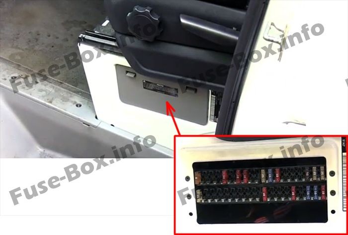
Location of the Fuse Box Under Driver’s Seat
As the name suggests, this fuse box is located beneath the driver’s seat. Accessing it usually involves moving or lifting the seat slightly, depending on your Sprinter model.
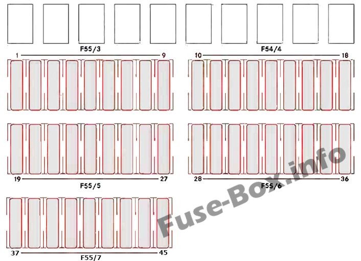
Fuse Box Diagram and Fuse Layout Under Driver’s Seat
This diagram illustrates the fuse box under driver seat Mercedes Sprinter, detailing each fuse and relay’s assignment in this location.
Fuse Box Under Driver’s Seat Fuse and Relay Assignment Chart
Fuse Block F55/3
| # | Consumer | Amp |
|---|---|---|
| 1 | Mirror setting/rear window defroster | 5 |
| 2 | Rear window wiper | 30 |
| 3 | Auxiliary heating, digital timer/rear view camera/neutral gate switch, starting-off aid and allwheel drive/engine runon/DIN slot basic wiring (roof)/FleetBoard/anti-theft protection with vehicle tracking/emergency hammer lighting in the rear compartment | 5 |
| 4 | Tachograph/ADR working speed governor/ power take-off/AAG (trailer control unit) | 7.5 |
| 5 | ECO Start/control unit EGS (electronic gearbox control) | 5/10 |
| 6 | All-wheel drive control unit Auxiliary oil pump | 5/10 |
| 7 | ESM (electronic selector module) | 10 |
| 8 | Loading tailgate/tipper vehicle PARKTRONIC (Vehicles with code XM0) | 10 |
| 9 | Rear compartment air conditioning, compressor clutch, disengagea-ble reverse warning device | 7.5 |
Fuse Block F55/4
| # | Consumer | Amp |
|---|---|---|
| 10 | Terminal 30, body/ equipment manufacturer | 25 |
| 11 | Terminal 15, body/ equipment manufacturer | 15 |
| 12 | D+, body/equipment manufacturer | 10 |
| 13 | Fuel pump FSCM / Fuel pump relay | 20/15 |
| 14 | Trailer power socket | 20 |
| 15 | Trailer recognition unit | 25 |
| 16 | Tire pressure monitor PARKTRONIC | 7.5 |
| 17 | Programmable special module (PSM) | 25 |
| 18 | Programmable special module (PSM) | 25 |
Fuse Block F55/5
| # | Consumer | Amp |
|---|---|---|
| 19 | Overhead control panel without ATA / Overhead control panel with ATA / Overhead control panel with rain sensor | 5/25/25 |
| 20 | License plate lamp /perimeter lamp /identification lighting | 7.5 |
| 21 | Terminal 30, body electrics / Rear window defroster without ATA / Rear window defroster with ATA | 15/30/15 |
| 22 | Rear window defroster 2 / Vehicle socket | 15/20 |
| 23 | 12 V left rear socket, load/rear compartment / Electric system: non-MB body | 15/10 |
| 24 | 12 V socket under the base of driver’s seat | 15 |
| 25 | 12 V right rear socket, load/rear compartment | 15 |
| 26 | Hot-water auxiliary heating | 25 |
| 27 | Electrical heater booster (PTC) Auxiliary warm-air heater | 25/20 |
Fuse Block F55/6
| # | Consumer | Amp |
|---|---|---|
| 28 | SRB starter relay / Starter for electrical supply support using the additional battery | 25 |
| 29 | Terminal 87 (7), gas system / Selective Catalytic Reduction control unit / Terminal 30, all-wheel drive, control unit | 7.5/10/30 |
| 30 | Auxiliary heat exchanger fan / Brake booster | 15/30 |
| 31 | Rear compartment heating blower Sliding door closing assistance, left Electric sliding door, left | 30/15/30 |
| 32 | Selective Catalytic Reduction relay supply / KEYLESS ENTRY | 5/10 |
| 33 | Electric sliding door, right Sliding door closing assistance, right ENR control unit Compressor air suspension | 30/15/30/30 |
| 34 | Selective Catalytic Reduction heater 3 DEF / Selective Catalytic Reduction heater 1 DEF | 15/20 |
| 35 | Selective Catalytic Reduction heater 2 hose / Selective Catalytic Reduction heater 2 DEF | 15/25 |
| 36 | Selective Catalytic Reduction heater 1 delivery pump / Selective Catalytic Reduction heater control 3 DEF | 10/15 |
Fuse Block F55/7
| # | Consumer | Amp |
|---|---|---|
| 37 | COLLISION PREVENTION ASSIST/FCW / Blind Spot Assist/BSM | 5/5 |
| 38 | Multifunction camera with Highbeam Assist / With a warning when leaving a lane | 10/10 |
| 39 | Body electrics / Rear-compartment air-conditioning system Roof ventilator Siren | 7.5/7.5/15/15 |
| 40 | Auxiliary battery charge current | 15 |
| 41 | SAM auxiliary battery reference voltage | 7.5 |
| 42 | Rear-compartment air-conditioning system | 30 |
| 43 | Electrical step/sliding door, right | 10 |
| 44 | Electrical step/sliding door, left | 10 |
| 45 | Electrical step, control system and warning buzzer | 5 |
Pre-Fuse Boxes
Pre-fuse boxes are high-current fuse locations, typically found closer to the battery and designed to protect major electrical components.
Pre-fuse Box in Battery Compartment
This pre-fuse box is located in the battery compartment, in the footwell on the left-hand side of the vehicle (F59).
Pre-fuse box F59 Fuse Assignment Chart
|