Maintaining your 2013 Mercedes-Benz C250 in top condition requires understanding its electrical system, and a crucial part of that is the fuse box. Fuses protect your vehicle’s electrical circuits from overloads, preventing damage to sensitive components. Knowing the location and function of each fuse is essential for troubleshooting electrical issues and performing basic maintenance.
The 2013 Mercedes-Benz C250, like many modern vehicles, utilizes multiple fuse boxes. For this model, you’ll find two primary fuse box locations: the Engine Compartment Fuse Panel and the Trunk Fuse Box. This guide will provide you with detailed diagrams and descriptions for both locations, ensuring you can quickly identify and address any fuse-related problems.
Engine Compartment Fuse Box Diagram
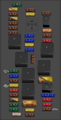
The main fuse box in your 2013 C250 is located in the engine compartment. This panel houses fuses and relays that protect critical engine and vehicle systems. Understanding this diagram is the first step in diagnosing many electrical issues.
This diagram illustrates the layout of the engine compartment fuse panel. Below is a detailed table outlining each fuse and relay, its amperage, and the components it protects. Refer to this table to pinpoint the exact fuse you need for your specific issue.
| Type | No. | Description |
|---|---|---|
| Fuse ATO 25A | 1 | Electronic Stability Program control unit |
| Fuse ATO 30A | 2 | Left front door control unit |
| Fuse ATO 30A | 3 | Valid up to 31.3.10: Right front door control unit Valid as of 1.4.10 with model 204.0/2/9: Right rear door control unit |
| Fuse ATO 7.5A | 4 | up to 31.8.08: Fuel pump control unit Valid for engine 156 up to 31.8.08: Left fuel pump control unit Right fuel pump control unit Valid for engine 642, engine 651: Fuel filter condensation sensor with heating element Valid for engine 651 up to 31.5.10, engine 646: Control unit for fuel filter condensation sensor with heating element |
| Fuse ATO 20A | 4 | Valid for diesel engine as of 1.9.08: Fuel filter condensation sensor with heating element Valid for engine 276 (USA, South Korea): Activated charcoal canister shutoff valve Valid for model 204.0/2/3 as of 1.3.11, 204.9 as of 1.6.12: Headlamp control unit |
| Fuse ATO 7.5A | 5 | Rear SAM control unit with fuse and relay module Valid as of 1.6.10 Exterior lights switch Valid for engine 156 Black Series as of 1.7.11: Rear axle differential coolant circuit relay |
| Fuse ATO 10A | 6 | Valid for diesel engine: ME-SFI [ME] control unit Valid for gasoline engine: CDI control unit |
| Fuse ATO 20A | 7 | Starter View problems with the starter fuse… |
| Fuse ATO 7.5A | 8 | Supplemental restraint system control unit |
| Fuse ATO 15A | 9 | Glove compartment power outlet |
| Fuse ATO 30A | 10 | Wiper motor |
| Fuse ATO 7.5A | 11 | Audio/COMAND display Audio/COMAND control panel Holder for navigation module |
| Fuse ATO 7.5A | 12 | Automatic air conditioning control and operating unit Upper control panel control unit |
| Fuse ATO 7.5A | 13 | Steering column module control unit Multifunction camera |
| Fuse ATO 7.5A | 14 | Electronic Stability Program control unit |
| Fuse ATO 20A | 14 | Headlamp control unit |
| Fuse ATO 7.5A | 15 | Supplemental restraint system control unit |
| Fuse ATO 5A | 16 | Diagnostic connector (up to 31.5.09) Mobile phone electrical connector Valid for transmission 722: Electronic selector lever module control unit |
| Fuse ATO 20A | 16 | ECO start/stop function: Electric transmission oil pump |
| Fuse ATO 30A | 17 | Panoramic sliding roof control module Overhead control panel control unit |
| Fuse ATO 7.5A | 18 | Valid up to 30.11.09: Exterior lights switch Valid for model 204.0/2 as of 1.3.11, model 204.3: Upper control panel control unit Valid for model 204.0/2 up to 28.2.11, model 204.9: Instrument panel climate control LIN positive line connector sleeve Vehicle interior and harness for taillamp electrical connector |
| Fuse ATO 20A | 19 | Electric steering lock control unit Electronic ignition lock control unit |
| Fuse MAXI 40A | 20 | Electronic Stability Program control unit |
| Fuse ATO 7.5A | 21 | Stop lamp switch Glove compartment lamp switch Front passenger seat occupied recognition and ACSR Electronic Toll Collection preinstallation electrical fuse (Japan) |
| Fuse ATO 15A | 22 | Combustion engine fan motor and air conditioning with integrated control Electrical connector for interior harness and engine wiring harness |
| Fuse ATO 20A | 23 | Electrical connector for interior harness and engine wiring harness Valid for diesel engine: Rear SAM control unit with fuse and relay module CDI control unit Terminal 87 connector sleeve Valid for engine 271: Terminal 87 M1e connector sleeve Valid for engine 272: Circuit 87 M1i connector sleeve |
| Fuse ATO 15A | 24 | Electrical connector for interior harness and engine wiring harness Interior and engine wiring harness electrical connector Valid for engine 642: Radiator shutters actuator Valid for engine 272: Terminal 87 M1e connector sleeve Valid for diesel engine: Terminal 87 connector sleeve Valid for engine 646: CDI control unit |
| Fuse ATO 15A | 25 | Valid for engine 156, 271, 272, 274, 276: ME-SFI [ME] control unit Valid for diesel engine: Oxygen sensor upstream of catalytic converter Valid as of 1.6.10 for model 204.3 with engine 651 Sport Edition: Exhaust system sound generator control unit |
| Fuse ATO 20A | 26 | Radio Radio with auto pilot system COMAND controller unit |
| Fuse ATO 7.5A | 27 | Electric steering lock control unit Electronic ignition lock control unit Valid for diesel engine: CDI control unit Valid for gasoline engine: ME-SFI [ME] control unit |
| Fuse ATO 7.5A | 28 | Instrument cluster |
| Fuse ATO 10A | 29 | Right front lamp unit |
| Fuse ATO 10A | 30 | Left front lamp unit Valid for engine 642: Electrical connector for interior harness and engine wiring harness |
| Fuse ATO 15A | 31A | Left fanfare horn Right fanfare horn |
| Fuse ATO 15A | 31B | Left fanfare horn Right fanfare horn |
| Fuse MAXI 40A | 32 | Valid for engine 156, 271, 272, 276: Electric air pump |
| Fuse MAXI 20A | 32 | Valid for engine 156: Oil cooler fan motor |
| Fuse ATO 10A | 33 | Valid for transmission 722.6: Electronic transmission-control control unit Valid for transmission 722.9: Fully integrated transmission control controller unit |
| Fuse ATO 7.5A | 34 | Valid for engine 271, 272 as of 1.9.08: Fuel pump control unit Valid for engine 156 as of 1.9.08: Left fuel pump control unit Right fuel pump control unit |
| Fuse ATO 5A | 35 | Valid as of 1.3.11: Electronic Stability Program control unit |
| Fuse ATO 7.5A | 36 | Valid as of 1.3.11: DISTRONIC electric controller unit Valid for model 204.902/982/984: Electrohydraulic power steering |
| Relay | J | Circuit 15 relay |
| Relay | K | Terminal 15R relay |
| Relay | L | Backup relay |
| Relay | M | Circuit 50 starter relay |
| Relay | O | Engine circuit 87 relay |
| Relay | O | Fanfare horn relay |
| Relay | P | Valid for engine 156, 272, 276: Secondary air injection relay |
| Relay | Q | Backup relay |
| Relay | R | Chassis circuit 87 relay |
Important Notes about the Engine Compartment Fuse Box:
- Fuse Types: This fuse box primarily uses ATO and MAXI fuses. Ensure you replace blown fuses with the same type and amperage rating to prevent electrical damage.
- Relays: Relays are also located in this box and control high-current circuits. If you suspect a relay issue, consult a professional technician for diagnosis and replacement.
- Variations: Mercedes-Benz vehicles can have slight variations depending on the specific model year, options, and engine type. Always double-check your vehicle’s owner’s manual for the most accurate fuse information.
Trunk Fuse Box Diagram
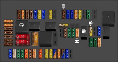
The second fuse box in your 2013 Mercedes-Benz C250 is located in the trunk, often referred to as the rear fuse box. This panel generally manages fuses for systems located in the rear of the vehicle and some comfort and convenience features.
This diagram outlines the layout of the trunk fuse box. The table below provides a detailed breakdown of each fuse and relay in this location.
| Type | No. | Description |
|---|---|---|
| Fuse ATO 5A | 37 | Driver seat NECK-PRO head restraint solenoid, Front passenger seat NECK-PRO head restraint solenoid |
| Fuse ATO 15A | 38 | Tailgate wiper motor |
| Fuse ATO 30A | 39 | ]Valid for model 204.0/2/9 except vehicles for Great Britain]: Left rear door control unit |
| Fuse ATO 30A | 41 | [Valid for model 204.0/2/9]: Right rear door control unit |
| Fuse ATO 25A | 42 | [Valid for gasoline engine or engine 651]: Fuel pump control unit |
| Fuse ATO 20A | 42 | [Valid for engine 646 or engine 642 or engine 651]: Fuel pump. [Valid for gasoline engine]: Fuel pump control unit View problems with the fuel pump fuse… |
| Fuse ATO 5A | 43 | Rear blower motor |
| Fuse ATO 30A | 44 | Switch group; right front seat setting, Front passenger seat partially electric seat adjustment switch |
| Fuse ATO 30A | 45 | Left front seat adjustment switch group, Driver seat partially electric seat adjustment switch |
| Fuse ATO 7.5A | 46 | Antenna amplifier for rear window FM antenna, Alarm siren, Interior protection and tow-away protection control unit, Rear window antenna amplifier 1, TV 1 antenna amplifier and, DAB Band III, DAB band III antenna, TV 2 antenna amplifier and KEYLESS-GO, KEYLESS-GO antenna amplifier |
| Fuse MAXI 40A | 49 | Rear window heater |
| Fuse MAXI 50A | 50 | Right front reversible emergency tensioning retractor |
| Fuse MAXI 50A | 51 | Left front reversible emergency tensioning retractor (A76) |
| Fuse ATO 15A | 53 | Trailer recognition control unit |
| Fuse ATO 7.5A | 54 | Trailer recognition control unit, [Valid for model 204.075/077/275/277]: Driver seat lumbar support and side bolster adjustment switch group, Front passenger seat lumbar support and side bolster adjustment switch group, Front passenger seat AMG valve block Driver seat AMG valve block |
| Fuse ATO 15A | 54 | Trailer recognition control unit |
| Fuse ATO 5A | 55 | AdBlue |
| Fuse ATO 15A | 56 | Trailer recognition control unit Trailer socket |
| Fuse ATO 5A | 56 | [Valid for model 204.077/277/377]: Driver seat lumbar support and side bolster adjustment switch group, Front passenger seat lumbar support and side bolster adjustment switch group, Front passenger seat AMG valve block Driver’s seat AMG valve block |
| Fuse ATO 20A | 57 | Trailer recognition control unit |
| Fuse ATO 20A | 58 | Trailer recognition control unit |
| Fuse ATO 5A | 59 | Parking system control unit, Left front bumper DISTRONIC (DTR) sensor, Right front bumper DISTRONIC (DTR) sensor, Intelligent radar sensor for left rear bumper, Intelligent radar sensor for right rear bumper |
| Fuse ATO 7.5A | 60 | Multicontour seat pneumatic pump |
| Fuse ATO 40A | 61 | Liftgate-control control unit |
| Fuse ATO 30A | 62 | Driver seat control unit |
| Fuse ATO 30A | 63 | Front passenger seat control unit |
| Fuse ATO 25A | 64 | DC/AC converter control unit |
| Fuse ATO 15A | 65 | Adaptive damping system control unit, Steering column tube module control unit |
| Fuse ATO 30A | 67 | Sound system amplifier control unit |
| Fuse ATO 20A | 69 | Rear bass speaker amplifier |
| Fuse ATO 5A | 70 | Tire pressure monitor control unit |
| Fuse ATO 15A | 71 | Front cigarette lighter with ashtray illumination, Front vehicle interior power outlet |
| Fuse ATO 15A | 72 | Cargo area connector box 115 V power outlet |
| Fuse ATO 7.5A | 73 | Diagnostic connector, Stationary heater radio remote control receiver, |
| Fuse ATO 15A | 74 | KEYLESS-GO control unit |
| Fuse ATO 20A | 75 | Stationary heater unit |
| Fuse ATO 15A | 76 | Vehicle interior power outlet |
| Fuse ATO 7.5A | 77 | Weight Sensing System (WSS) control unit |
| Fuse ATO 7.5A | 78 | Left front seat ventilation blower regulator, Right front seat ventilation blower regulator |
| Fuse ATO 5A | 79 | Parking system control unit |
| Fuse ATO 7.5A | 80 | Video and radar sensor system control unit, Parking system control unit |
| Fuse ATO 5A | 81 | Media interface control unit |
| Fuse ATO 5A | 82 | Cellular telephone system compensator UMTS, TV tuner control unit [Japan], Digital TV tunern [Japan] |
| Fuse ATO 7.5A | 83 | Electronic Toll Collection control unit [Japan], Emergency call system control unit, Reversing camera, Left rear display, Right rear display |
| Fuse ATO 7.5A | 84 | Satellite digital audio radio (SDAR) control unit, SDAR/high definition tuner control unit, Digital Audio Broadcasting control unit, Backup camera power supply module, Backup camera control unit, 360° camera control unit |
| Fuse ATO 7.5A | 85 | [Japan]: TV tuner control unit or Digital TV tuner |
| Fuse ATO 7.5A | 86 | DVD player |
| Fuse ATO 7.5A | 87 | Emergency call system control unit |
| Fuse ATO 20A | 89 | Trailer recognition control unit, [With engine 156]: Oil cooler fan motor relay |
| Fuse ATO 40A | 90 | AdBlue fuse block, AdBlue supply relay |
| Fuse ATO 25A | 91 | DC/AC converter control unit |
| Fuse ATO 20A | 91 | ECO start/stop: Transmission oil auxiliary pump control unit. [Valid for engine 642]: Vent line heater element |
| Relay | A | Terminal 15 relay |
| Relay | B | Circuit 15R relay (1) |
| Relay | C | Heated rear window relay |
| Relay | D | [Diesel]: Fuel pump relay View problems with the fuel pump relay… |
| Relay | E | Tailgate windshield wiper relay |
| Relay | F | Seat adjustment relay |
| Relay | G | Circuit 15R relay (2) |
Key Considerations for the Trunk Fuse Box:
- Power-Intensive Systems: Notice that many fuses in the trunk fuse box are related to power seats, rear window functions, and audio systems, which are often power-intensive.
- Trailer Systems: If your 2013 C250 is equipped with a trailer hitch, you’ll find fuses related to the trailer recognition and electrical connections in this rear fuse box.
- Access: Trunk fuse boxes are usually easily accessible, often located behind a trim panel in the trunk lining. Refer to your owner’s manual for the exact location.
Troubleshooting and Fuse Replacement Tips
When dealing with fuses in your 2013 Mercedes-Benz C250, remember these important tips:
- Consult Your Owner’s Manual: Your vehicle’s owner’s manual is the most reliable source for fuse box diagrams and fuse assignments specific to your car. Diagrams can sometimes vary slightly.
- Identify the Correct Fuse: Use the diagrams and tables provided to accurately locate the fuse associated with the malfunctioning component.
- Visual Inspection: Remove the suspected fuse and visually inspect it. A blown fuse will typically have a broken wire inside.
- Proper Replacement: Always replace a blown fuse with a fuse of the exact same type and amperage rating. Using a fuse with a higher amperage can overload the circuit and cause serious damage or even a fire.
- Test After Replacement: After replacing the fuse, test the affected component to ensure it is now working correctly.
- Seek Professional Help: If fuses repeatedly blow, or if you are unsure about troubleshooting electrical issues, it’s best to consult a qualified Mercedes-Benz technician. This could indicate a more serious underlying electrical problem.
Understanding your 2013 Mercedes-Benz C250 fuse box diagram is a valuable skill for any owner. By using this guide and practicing safe troubleshooting, you can maintain your vehicle’s electrical system and address minor issues efficiently. Remember to prioritize safety and consult professionals when needed to keep your Mercedes-Benz running smoothly.