Maintaining the electrical system of your 2007 Mercedes S550 is crucial for its overall performance and longevity. A key component of this system is the fuse box, which protects your vehicle’s electrical circuits from damage caused by overloads. Understanding the location and function of each fuse within the fuse box is essential for troubleshooting electrical issues. Unlike some vehicles with a single fuse box, the 2007 Mercedes S550 is equipped with four distinct fuse boxes, each serving different areas of the car. This guide will help you locate these fuse boxes and understand their diagrams, ensuring you can effectively diagnose and resolve any fuse-related problems in your Mercedes S550.
To properly address any electrical concerns, knowing where each fuse box is situated is the first step. The 2007 Mercedes S550 has strategically placed fuse boxes in the instrument panel (both left and right sides), the rear of the vehicle, and the engine compartment. Each of these locations houses fuses that control specific systems and components of your car. By familiarizing yourself with these locations and their corresponding diagrams, you can save time and effort when diagnosing electrical faults. Below, we provide a detailed overview of each fuse box location and its diagram to assist you in maintaining your 2007 Mercedes S550.
Instrument Panel Fuse Box [Left] Diagram
The first fuse box is located within the instrument panel on the left-hand side of the vehicle. Accessing this fuse box typically involves removing a cover panel, often found at the end of the dashboard, visible when the driver’s door is open. This fuse box primarily manages circuits related to interior functions and convenience features within the car.
| Type | No. | Description |
|---|---|---|
| Fuse ATO 40A | 92 | Left front seat control unit |
| Fuse ATO 7.5A | 93 | Restraint systems control unit USA version: Weight Sensing System (WSS) control unit |
| Fuse ATO 5A | 94 | from 2009: Multifunction camera |
| Fuse ATO 5A | 96 | Tire pressure monitor [RDK] control unit |
| Fuse ATO 7.5A | 97 | W221: Audio/video controller control unit (rear entertainment system) |
| Fuse ATO 7.5A | 98 | Rear entertainment system: DVD player (from 2009) |
| Fuse ATO 7.5A | 99 | from 2009: COMAND display, SPLITVIEW display |
| Fuse ATO 5A | 100 | from 2009: Media interface control unit |
| Fuse ATO 10A | 101 | Rear entertainment system: Left rear display, Right rear display |
| Fuse ATO 40A | 102 | Right front seat control unit |
| Fuse ATO 7.5A | 103 | ESP control unit |
| Fuse ATO 40A | 104 | Audio tuner control unit |
| Fuse ATO 1A | 106 | Japanese version: Electronic toll collection (ETC) control unit Valid for South Korea as of 1.9.10: TV/tuner connector Valid for navigation; from 2009: Navigation processor |
| Fuse ATO 5A | 107 | SDAR control unit (SIRIUS satellite radio) (W221 from 2009) Digital radio: Digital Audio Broadcasting control unit HD radio: High definition tuner control unit |
| Fuse ATO 5A | 108 | W221: Rear air conditioning control unit |
| Fuse ATO 15A | 109 | W221: Rear blower intermediate connector |
| Fuse ATO 7.5A | 110 | W221: Left rear multicontour backrest control unit, Right rear multicontour backrest control unit |
| Fuse ATO 5A | 111 | Rear multicontour seat or rear entertainment system (model 221): RCP [HBF] control unit |
| Fuse ATO 5A | 112 | W221; up to 2008: Left front door control unit, Right front door control unit S 400 Hybrid: Front SAM control unit with fuse and relay module |
| Fuse ATO 5A | 113 | S400 Hybrid: DC/DC converter control unit |
Instrument Panel Fuse Box [Right] Diagram
Similar to the left side, the right side of the instrument panel also houses a fuse box. This is typically accessed in the same manner as the left side, by removing a cover panel at the end of the dashboard when the passenger door is opened. This fuse box, like its counterpart, manages various interior electrical functions, potentially including passenger-side specific features and shared systems.
| Type | No. | Description |
|---|---|---|
| Fuse ATO 40A | 70 | C216: Right door control unit W221: Right front door control unit |
| Fuse ATO 15A | 71 | Keyless Go control unit |
| Fuse ATO 7.5A | 72 | S 400 Hybrid: Pyrotechnical separator |
| Fuse ATO 5A | 73 | Japanese version: COMAND controller unit TELE AID emergency call system (from 2009): Emergency call system control unit |
| Fuse ATO 30A | 74 | TLC [HDS] control unit (Remote trunk closing) |
| Fuse ATO 10A | 75 | S 400 Hybrid: Battery management system control unit, Power electronics control unit |
| Fuse ATO 15A | 76 | S 400 Hybrid: Vacuum pump relay (+) |
| Fuse ATO – | 77 | Advanced Sound system |
| Fuse ATO 25A | 78 | S 65 AMG with engine 275: Additional fan relay (from 2009) Valid for model 221 with engine 642.8: AdBlue relay supply (from 2009) |
| Fuse ATO 15A | 78 | S 400 Hybrid, CL 63 AMG with engine 157, 278: Charge air cooler circulation pump (from 2009) |
| Fuse ATO 7.5A | 79 | Alarm signal horn with additional battery |
| Fuse ATO 40A | 80 | C216: Left door control unit W221: Left front door control unit |
| Fuse ATO 30A | 81 | C216: Rear control unit |
| Fuse ATO 40A | 81 | W221: Left rear door control unit |
| Fuse ATO 30A | 82 | C216: Rear control unit |
| Fuse ATO 40A | 82 | W221: Left rear door control unit |
| Fuse ATO 30A | 83 | Intelligent servo module for DIRECT SELECT |
| Fuse ATO 20A | 84 | Advanced sound system: Digital sound processor (from 2009) |
| Fuse ATO 10A | 85 | Valid for AMG: Illuminated door sill moldings (from 2009) |
| Fuse ATO 20A | 90 | Stationary heater: STH heater unit (C216), STH or HB heater unit (W221) |
| Fuse ATO 5A | 91 | Stationary heater: STH radio remote control receiver S 400 Hybrid: Front SAM control unit with fuse and relay module |
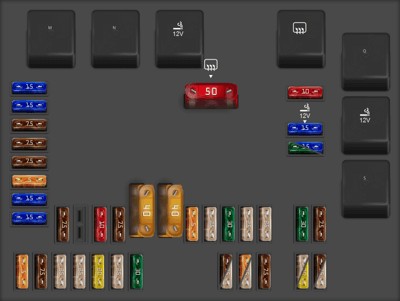
Rear Fuse Box Diagram
Moving to the rear of the vehicle, the rear fuse box in the 2007 Mercedes S550 is typically located in the trunk or luggage compartment. Its exact placement can vary slightly but is often behind a trim panel on one side of the trunk. This fuse box is responsible for circuits powering rear vehicle systems, including lighting, trunk functions, and potentially rear passenger amenities.
| Type | No. | Description |
|---|---|---|
| Fuse MAXI 50A | 115 | Heated rear window |
| Fuse ATO 10A | 116 | Valid for engine 157, 275, 278: Charge air cooler circulation pump Valid for engine 156: Engine coolant circulation pump S 400 Hybrid: Power electronics circulation pump 2 |
| Fuse ATO 15A | 117 | Rear cigar lighter |
| Fuse ATO 30A | 118 | Valid for engine 272, 273, 642: Fuel pump (up to 2008) Valid for model 221 with engine 629, 642: Fuel pump (from 2009) |
| Fuse ATO 15A | 118 | S 400 Hybrid: Power electronics circulation pump 1 Valid for model 642.8 and engine 651 as of 1.6.11: Refrigerant compressor with magnetic |
| Fuse ATO 7.5A | 119 | Front central operating unit |
| Fuse ATO 10A | 121 | Audio tuner control unit |
| Fuse ATO 7.5A | 122 | COMAND controller unit |
| Fuse MAXI 40A | 123 | W221: Right front reversible emergency tensioning retractor |
| Fuse MAXI 40A | 124 | W221: Left front reversible emergency tensioning retractor |
| Fuse ATO 5A | 125 | up 31.5.09: Voice control system (VCS) control unit |
| Fuse ATO 25A | 126 | Overhead control panel control unit |
| Fuse ATO 30A | 127 | Lumbar pump (from 2009) Multicontour seat pneumatic pump (Left/right front multicontour seats) Pneumatic pump for dynamic seat control (Left and right dynamic multicontour seat) |
| Fuse ATO 25A | 128 | Valid for engine 275 (up to 2008): Fuel pump control unit Valid for engine 156, 157, 272, 273, 275, 276, 278, 642 (from 2009): Fuel pump control unit |
| Fuse ATO 25A | 129 | up to 2008: Overhead control panel control unit (Power glass tilting/sliding roof) from 2009: UPCI (Universal Portable Cell Phone Interface) control unit |
| Fuse ATO 30A | 130 | Electric parking brake controller unit |
| Fuse ATO 7.5A | 131 | Rear window antenna amplifier module |
| Fuse ATO 15A | 133 | Trailer recognition control unit Reversing camera (as of 1.9.10) |
| Fuse ATO 15A | 134 | Luggage compartment socket |
| Fuse ATO 7.5A | 135 | Park Assist; up 2008: Radar sensors control unit (SGR) Front short range radar sensor unit Rear short range radar sensor unit DISTRONIC PLUS up to 31.8.10 or Blind Spot Assist or Adaptive cruise control Plus Light: Radar sensors control unit (SGR) (from 2009) PARKTRONIC or Exclusive parking assist: PTS control unit |
| Fuse ATO 7.5A | 136 | Valid for model 221 with engine 642.8: AdBlue® control unit |
| Fuse ATO 7.5A | 137 | Reversing camera (as of 1.9.10) |
| Fuse ATO 5A | 138 | Navigation processor (from 2009) (up to 31.8.10) Emergency call system control unit (from 2009) Japanese version: TV/tuner connector (from 2009) |
| Fuse ATO 15A | 139 | Rear backrest refrigerator box |
| Fuse ATO 15A | 140 | Rear cigar lighter with ashtray illumination connector 115 V socket (from 2009) |
| Fuse ATO 5A | 141 | Reversing camera control unit |
| Fuse ATO 7.5A | 142 | Parktronic system (PTS) control unit Distronic Plus: Radar sensors control unit (SGR) Valid as of 1.9.10 for DISTRONIC PLUS and Active Blind Spot Assist or Active Lane Keeping Assist: Video and radar sensor system control unit |
| Fuse ATO 25A | 143 | Rear seats control unit |
| Fuse ATO 25A | 144 | Rear seats control unit |
| Fuse ATO 20A | 145 | Trailer recognition control unit (up to 2008) Trailer hitch socket (13-pin) (from 2009) |
| Fuse ATO 25A | 146 | Trailer recognition control unit |
| Fuse ATO 30A | 147 | up to 2008: TLC [HDS] control unit (Remote trunk closing) |
| Fuse ATO 7.5A | 148 | up to 2008: Universal Portable CTEL Interface (UPCI [UHI]) control unit |
| Fuse ATO 25A | 148 | from 2009: Panoramic sliding sunroof circuit 30 connector sleeve |
| Fuse ATO 5A | 149 | up to 2008: Voice control system (VCS [SBS]) control unit |
| Fuse ATO 25A | 149 | from 2009: Panoramic sliding sunroof control module |
| Fuse ATO 7.5A | 150 | TV combination tuner (analog/digital) Japanese version: TV/tuner connector (from 2009) |
| Fuse ATO 25A | 151 | W221; up to 2008: Electric parking brake controller unit |
| Fuse ATO 20A | 151 | W221; from 2009: Trailer recognition control unit |
| Fuse ATO 7.5A | 152 | W221: Rear window antenna amplifier module |
| Fuse ATO 25A | 152 | 115 V socket: DC/AC converter control unit |
| Relay | M | Terminal 15 relay |
| Relay | N | Terminal 15R relay |
| Relay | O | Power outlet relay |
| Relay | P | Heated rear window relay |
| Relay | Q | Valid for engine 156, 157, 275, 278, 629: Circulation pump relay S 400 Hybrid: Valid for model 221.095/195: Power electronics circulation pump relay 2 |
| Relay | R | Cigar lighter relay |
| Relay | S | Fuel pump relay Valid for engine 642.8 and engine 651 as of 1.6.11: Connected through the fuel pump: Refrigerant compressor magnetic clutch S 400 Hybrid: Power electronics circulation pump relay 1 |
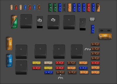
Engine Compartment Fuse Box Diagram
The final fuse box is located in the engine compartment. Its specific location can vary based on the engine configuration but is generally found near the battery or the main engine control unit. This fuse box manages critical engine and powertrain related circuits, including engine management, ignition, and other essential operational components.
| Type | No. | Description |
|---|---|---|
| Fuse ATO 10A | 20 | Valid for engine 629, 642, 651: CDI control unit, Valid for engines 156, 157, 272, 273, 275, 276, 278: ME-SFI [ME] control unit |
| Fuse ATO 20A | 21 | Valid for engines 156, 157, 272, 273, 275, 276, 278: Terminal 87 MI i connector sleeve, Valid for model 221 with engine 629 and engine 642: CDI control unit Fuel pump relay, Valid for model 221 with engine 651: Quantity control valve |
| Fuse ATO 15A | 22 | Valid for engines 156, 157, 272, 273, 276, 278: Terminal 87 connector sleeve |
| Fuse ATO 20A | 23 | up to 2008: Terminal 87 connector sleeve, Valid for engine 275 (model 216): Terminal 87 M1 i connector sleeve. Valid for engine 273 (model 216): Terminal 87 M2e connector sleeve. Valid for engine 272, 273 (model 221): Terminal 87M2i connector sleeve. Valid for engine 642: Terminal 87 connector sleeve. From 2009: Valid for engine 156, 157, 272, 273, 275, 276, 278: Terminal 87 connector sleeve. Valid for model 221 with engine 629 and engine 642: Terminal 87 connector sleeve. Valid for engine 156, 157, 272, 273, 276, 278: Terminal 87M2e connector sleeve. Valid for engine 275: Terminal 87 M2i connector sleeve. Valid for model 221 with engine 629 and engine 642: Terminal 87 connector sleeve. Valid for model 221 with engine 651: Rear SAM control unit with fuse and relay module. |
| Fuse ATO 25A | 24 | Valid for engines 157, 272, 273, 276, 278: Terminal 87Mle connector sleeve Valid for engine 642: CDI control unit |
| Fuse ATO 7.5A | 25 | Instrument cluster |
| Fuse ATO 10A | 26 | Left front lamp unit |
| Fuse ATO 10A | 27 | Right front lamp unit |
| Fuse ATO 7.5A | 28 | Valid for engine 275: EGS control unit Valid without engine 275: Fully integrated transmission control (VGS) control unit |
| Fuse ATO 5A | 29 | Rear SAM control unit with fuse and relay module |
| Fuse ATO 7.5A | 30 | Valid for engine 629, 642, 651: CDI control unit Valid for engines 156, 157, 272, 273, 275, 276, 278: ME-SFI [ME] control unit Fuel pump control unit |
| Fuse ATO 5A | 31 | S 400 Hybrid: Electric refrigerant compressor |
| Fuse ATO 15A | 32 | Valid for model with ECO start/stop function: Transmission oil auxiliary pump control unit S 400 Hybrid: Transmission oil auxiliary pump control unit |
| Fuse ATO 5A | 33 | Valid as of 1.9.10 without model is 400 Hybrid: ESP control unit S 400 Hybrid: Battery management system control unit DC/DC converter control unit Power electronics control unit |
| Fuse ATO 5A | 34 | 400 Hybrid: Regenerative braking system control unit |
| Fuse ATO 5A | 35 | Electric parking brake controller unit |
| Fuse ATO 10A | 36 | Data link connector (Pin 16) |
| Fuse ATO 7.5A | 37 | For EIS control unit |
| Fuse ATO 7.5A | 38 | Central gateway control unit |
| Fuse ATO 7.5A | 39 | Instrument cluster |
| Fuse ATO 7.5A | 40 | Upper control panel control unit |
| Fuse ATO 30A | 41 | Slave wiper motor |
| Fuse ATO 30A | 42 | Master wiper motor |
| Fuse ATO 15A | 43 | Front cigar lighter with ashtray illumination |
| Fuse ATO | 44 | – |
| Fuse ATO 5A | 45 | S 400 Hybrid: Power electronics circulation pump 1 |
| Fuse ATO 15A | 46 | W221 with Active Body Control (ABC), model 216: ABC control unit W221 without Active Body Contro (ABC): AIRmatic with ADS control unit |
| Fuse ATO 15A | 47 | Front SAM control unit with fuse and relay module Steering column up/down motor |
| Fuse ATO 15A | 48 | up to 2008: Front SAM control unit with fuse and relay module from 2009: Steering column in/out motor |
| Fuse ATO 10A | 49 | Steering column module |
| Fuse ATO 15A | 50 | AAC [KLA] control unit |
| Fuse ATO 7.5A | 51 | up to 2008: COMAND display |
| Fuse ATO 5A | 51 | from 2009: COMAND display SPLITVIEW display |
| Fuse FMM/MCase 15A | 52A | W221: Left fanfare horn Right fanfare horn |
| Fuse ATO 15A | 52B | W221, C216: Left fanfare horn Right fanfare horn |
| Fuse MAXI | 53 | – |
| Fuse MAXI 40A | 54 | AC air recirculation unit |
| Fuse MAXI 60A | 55 | Valid for gasoline engine: Electric air pump |
| Fuse MAXI 40A | 56 | W221 without Active Body Contro (ABC): AIRmatic compressor unit |
| Fuse MAXI 40A | 57 | up 2008: Wiper park position heater |
| Fuse MAXI 30A | 57 | from 2009: Wiper park position heater |
| Fuse MINI 5A | 60 | from 2009: Electrohydraulic power steering |
| Fuse MINI 7.5A | 61 | C216;W221-from 2009: Restraint systems control unit |
| Fuse MINI 10A | 61 | W221; up to 2008: Restraint systems control unit |
| Fuse MINI 5A | 62 | Night View Assist control unit |
| Fuse MINI 15A | 63 | Valid for model 221 with engine 629 and engine 642 as of 1.9.08: Fuel filter condensation sensor with heating element |
| Fuse MINI 7.5A | 64 | W221 as of 1.9.06: Driver NECK-PRO head restraint solenoid, Front passenger NECK-PRO head restraint solenoid |
| Fuse MINI 10A | 64 | W221 as of ’09: Driver NECK-PRO head restraint solenoid, Front passenger NECK-PRO head restraint solenoid |
| Fuse MINI 15A | 65 | Valid as of 1.6.09: 12 Volt connector in glove box |
| Fuse MINI 7.5A | 66 | DTR controller unit (Distronic or Distronic Plus) |
| Relay | A | Air pump relay |
| Relay | B | Air suspensión compressor relay |
| Relay | C | Terminal 87 relay, engine |
| Relay | D | Terminal 15 relay |
| Relay | E | Terminal 87 relay, chassis |
| Relay | F | Fanfare horn relay |
| Relay | G | Terminal 15R relay |
| Relay | H | Circuit 50 relay, starter View problems with the starter relay… |
| Relay | J | Circuit 15 relay, starter View problems with the starter relay… |
| Relay | K | Wiper park heater relay |
By understanding the locations and diagrams of these four fuse boxes, you can effectively troubleshoot and maintain the electrical system of your 2007 Mercedes S550. Always refer to your vehicle’s owner’s manual for the most accurate and up-to-date information regarding fuse box locations and fuse assignments, as specifications can sometimes vary based on production date and optional equipment. Regularly checking your fuses is a simple yet crucial step in preventing more significant electrical problems and ensuring your Mercedes S550 remains in top operating condition.